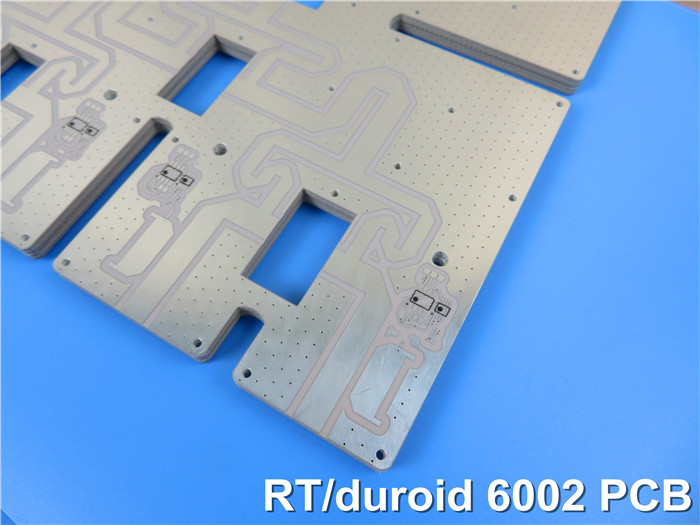
Rogers RT/Duroid 6002 High Frequency PCB with 10mil, 20mil, 30mil and 60mil Coating Immersion Gold and Immersion Silver
(Note: PCBs are custom-made products; the images and specifications shown are for reference only.)
Hello everyone,
Today, we talk about the high frequency PCB made on RT/duroid 6002 material.
Overview of RT/Duroid 6002 Material
RT/Duroid 6002 is a premier low-loss, low-dielectric-constant laminate designed to meet stringent requirements for mechanical reliability and electrical stability in complex microwave structural designs. This material primarily consists of PTFE ceramic composites.
The dielectric constant of RT/Duroid 6002 exhibits exceptional resistance to temperature fluctuations between -55°C and +150°C, making it suitable for applications involving filters, oscillators, and delay lines that demand electrical stability.
Key Advantages of RT/Duroid 6002 PCBs
1.Low Loss: Ensures outstanding high-frequency performance.
2.Mechanical and Electrical Reliability: Robust multi-layer board construction.
3.Dimensional Stability: Extremely low thermal coefficient of dielectric constant.
4.In-Plane Expansion Compatibility: Matched to copper, enhancing surface-mounted assembly reliability.
5.Low Outgassing: Ideal for space applications.
Typical Applications
Phased Array Antennas
Ground-Based and Airborne Radar Systems
GPS Antennas
Power Backplanes
Commercial Airline Collision Avoidance Systems
PCB Capabilities (RT/Duroid 6002)
PCB Material: |
Ceramic-filled PTFE composite |
Designation: |
RT/duroid 6002 |
Dielectric constant: |
2.94 ±0.04 (process) |
2.94 (design) |
|
Layer count: |
2 Layer, Multilayer |
Copper weight: |
0.5oz (17 µm), 1oz (35µm), 2oz (70µm) |
PCB thickness: |
10mil (0.254mm), 20mil (0.508mm) |
30mil (0.762mm), 60mil (1.524mm), 120mil (3.048mm) |
|
PCB size: |
≤400mm X 500mm |
Solder mask: |
Green, Black, Blue, Yellow, Red etc. |
Surface finish: |
Bare copper, HASL, ENIG, Immserion Silver, OSP etc.. |
The base copper options for RT/Duroid PCBs include 0.5oz, 1oz, and 2oz, with a wide range of PCB thicknesses from 5mil to 120mil available for our designers’ consideration.
The standard color for RT/Duroid 6002 PCBs is white. This material is highly suited for both flat and non-planar structures, including antennas, complex multi-layer circuits with inner-layer connections, and microwave circuits designed for aerospace applications in challenging environments.
If you have any questions or require further information, please feel free to contact us. Thank you for reading!
Appendix: Data Sheet of RT/Duroid 6002
RT/duroid 6002 Typical Value |
|||||
Property |
RT/duroid 6002 |
Direction |
Units |
Condition |
Test Method |
Dielectric Constant,εProcess |
2.94±0.04 |
Z |
|
10 GHz/23℃ |
IPC-TM-650 2.5.5.5 |
Dielectric Constant,εDesign |
2.94 |
|
|
8GHz to 40 GHz |
Differential Phase Length Method |
Dissipation Factor,tanδ |
0.0012 |
Z |
|
10 GHz/23℃ |
IPC-TM-650 2.5.5.5 |
Thermal Coefficient of ε |
+12 |
Z |
ppm/℃ |
10 GHz 0℃-100℃ |
IPC-TM-650 2.5.5.5 |
Volume Resistivity |
106 |
Z |
Mohm.cm |
A |
ASTM D 257 |
Surface Resistivity |
107 |
Z |
Mohm |
A |
ASTM D 257 |
Tensile Modulus |
828(120) |
X,Y |
MPa(kpsi) |
23℃ |
ASTM D 638 |
Ultimate Stress |
6.9(1.0) |
X,Y |
MPa(kpsi) |
||
Ultimate Strain |
7.3 |
X,Y |
% |
||
Compressive Modulus |
2482(360) |
Z |
MPa(kpsi) |
|
ASTM D 638 |
Moisture Absorption |
0.02 |
|
% |
D48/50 |
IPC-TM-650 2.6.2.1 |
Thermal Conductivity |
0.6 |
|
W/m/k |
80℃ |
ASTM C518 |
Coefficient of Thermal Expansion |
16 |
X |
ppm/℃ |
23℃/50% RH |
IPC-TM-650 2.4.41 |
Td |
500 |
|
℃ TGA |
|
ASTM D 3850 |
Density |
2.1 |
|
gm/cm3 |
|
ASTM D 792 |
Specific Heat |
0.93(0.22) |
|
j/g/k |
|
Calculated |
Copper Peel |
8.9(1.6) |
|
Ibs/in.(N/mm) |
|
IPC-TM-650 2.4.8 |
Flammability |
V-0 |
|
|
|
UL 94 |
Lead-free Process Compatible |
Yes |
|
|
|
|